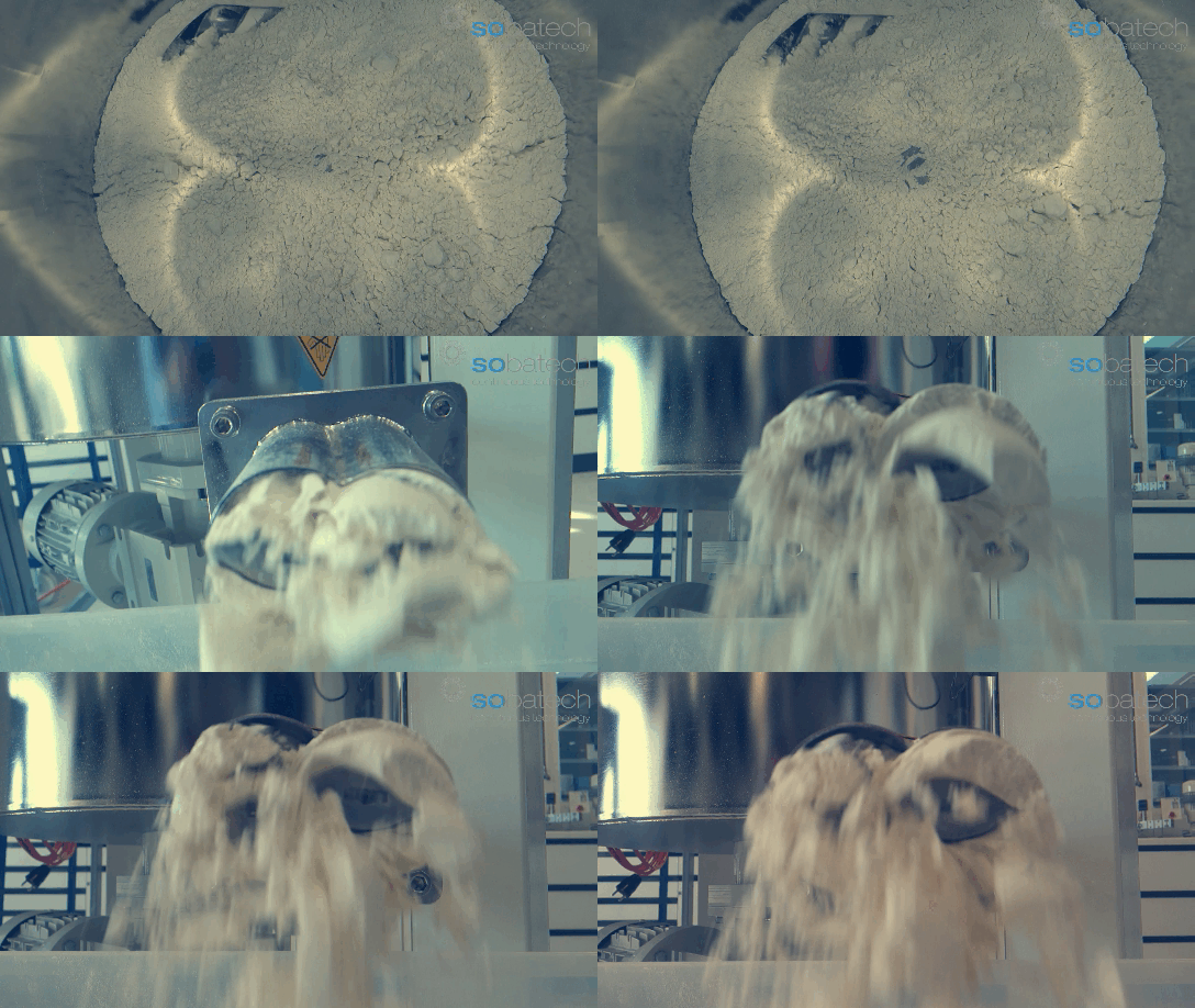
GRAVIMETRIC DOSING SOLIDS
Sobatech doses its ingredients into the continuous mixing system by means of gravimetric feeding solutions. A gravimetric feeder doses the actual given weight of material per time unit. In such system, the motor automatically alters its speed when a change is detected in the material flow. This eliminates the need for manual adjustment, which ís required when using a volumetric feeder. Such a change in material flow can for instance be the result of the addition of new material or fluctuations in the material density.
In a continuous production process, the dosing of ingredients need to be accurate every split second. Therefore, it is recommended to only work with gavimetric dosing solutions as these are the most accurate and precise feeding solutions available. Sobatech works with so called loss-in-weight feeders which are gravimetric dosing systems and measure the weight reduction per time unit.
LOSS-IN-WEIGHT FEEDER CHALLENGES
Generally, there are three challenges to take into consideration when it comes to loss-in-weight dosing.
- The influence of external forces on the weight sensing device (loadcells)
- The controlling of the motor speed during refilling (gain in weight)
- Powder bridging and arching in the dosing hopper
1. THE INFLUENCE OF EXTERNAL FORCES ON THE LOADCELLS
Generally a loss in weight feeder interacts with the process by receiving and discharging material. Yet, it has to remain isolated from other process equipment in the plant for maximum weigh accuracy. Sophisticated digital filtering algorithms can be applied to recognize and ignore brief disturbances. However, the cumulative effect of ongoing disturbance degrade overall feeder performance.
Loss in weight systems must often commit to extreme high dosing accuracies meaning that very small changes in total system weight have to be detected. This requires a very high resolution yet stable weighing system that is unaffected by environmental variations. In-plant shock and vibrations can corrupt the weight measurement, destroying the basis for feed rate control. What helps preventing this are:
- Flexible connections between the dosing unit and other parts of the system.
- Ensure that the dosing hopper has a stable mounting frame.
- Use shock mounts to help isolate the feeding system and filter out the accelerations associated with the plant environment
- Eliminate strong air currents near the dosing unit
2. THE CONTROLLING OF MOTOR SPEED DURING REFILLING (GAIN-IN-WEIGHT)
During hopper refill, system weight increases and clearly cannot be used as a basis for feed rate control. There are two ways how to deal with this so called gain-weight-process.
THE CONVENTIONAL METHOD
The conventional method is to use a constant metering speed throughout the refill phase. the moment an increase in weight is sensed, the feeder maintains the RPM measured just before the refill process started. As in this method the material feed during refilling is maintained by keeping a constant metering speed, the feeder essentially functions volumetrically. When the refill phase is complete and the material has settled, the feeder senses the declining system weight and returns to gravimetrical operation with the metering speed once again being determined by the actual loss in weight.
Depending on the process material compressibility, this traditional approach may or may not generate a sensed weight disturbance as the feeder returns to gravimetric operation. For an easily compressible material for which density changes significantly as a result of so called headload, feeder speed just before refill is somewhat higher that it should be after refill when the material being fed was compressed due to the applied weight of newly added material.
As a result, when feeder speed is held constant at this higher speed, overfeeding may occur during refill, and feeder speed is abruptly reduced when gravimetric operation resumes. Such abrupt changes in feeder speed can occur resulting in a (sometimes extended) period of off-spec flow until the feeder settles at the new, proper speed.
THE ALTERNATIVE METHOD
Some feeders avoid this shortcoming by memorizing the feeder’s recent weighing history and using that information to smoothly reduce feeder speed during the short refill period. This brings us to the alternative and at the same time best method for managing gain in weight. In this alternative method the feeders weight-to-speed ratio during gravimetric feeding is stored and that data is then used to control the feeder speed during volumetric feeding in the refill phase. In practice this means that the information that connects a certain filling level of the hopper to the corresponding screw speed is memorized. This way – the system can, even though it is dosing volumetrically during refilling, eliminate the effects of increased density as a result of compressibility of the refilling process.
3. FLOW THROUGH THE FEEDER PROBLEMS
As the feeder tries to empty the powders below the blockage, the feed rate falls to zero; while the hopper net weight remains the same. Thereafter, feeder speed maxes out in its attempt to dose material that is no longer available. Then, weight loss drops to zero. In a trend line pattern typical of material buildup, weight loss per screw revolution declines more than expected over time as material builds up on the dosing screws.
In response, feeder speed increases to compensate for the efficiency reduction. Too much build up could eventually trigger an alarm condition related to feeder speed or violation of weight loss per screw rotation limits. This condition could arise from any of several causes including a different ingredient supplier, changes in storage, temperature or transport practices. Generally, there are two types of flow through feeder problems.
ARCHING (BRIDGING)
Arching (bridging) occurs when an arch-shaped obstruction forms above the hopper outlet and stops flow. It can be an interlocking arch, where large particles mechanically interlock to form an obstruction, or a cohesive arch. A cohesive arch occurs when particles bond together due to effects of moisture, fines concentration, particle shape, temperature, etc.
RATHOLING
Ratholing occurs when discharge takes place only in a flow channel located above the outlet. If the material being handled is cohesive, the material outside of this channel will not flow into it and may cake or agglomerate.
Solutions to prevent arching and ratholing from happening are vibrating units, air pads, and/or stirring devices.


